Metronome v2.0
Table of Contents
Introduction #
During my first semester of Electrical Engineering back in 2007, I had an introduction to electronics class where by the end of the semester we had to develop an open project. At first, I tried to build an AM radio using only passive components. I remember that after hours placing components on the breadboard, I managed to make it work, but it was really inconsistent and super noisy. The project was working, but it wasn’t as good as I wanted, so I decided to build something else, something that could be actually useful, and that’s when the metronome idea came alive. Using a few components and a 555 IC, I could make the circuit “tick” in a frequency that can be used for your music studies.
A few weeks ago, I decided to revive the project, but this time creating a better-looking PCB, where people could use it to learn to solder.
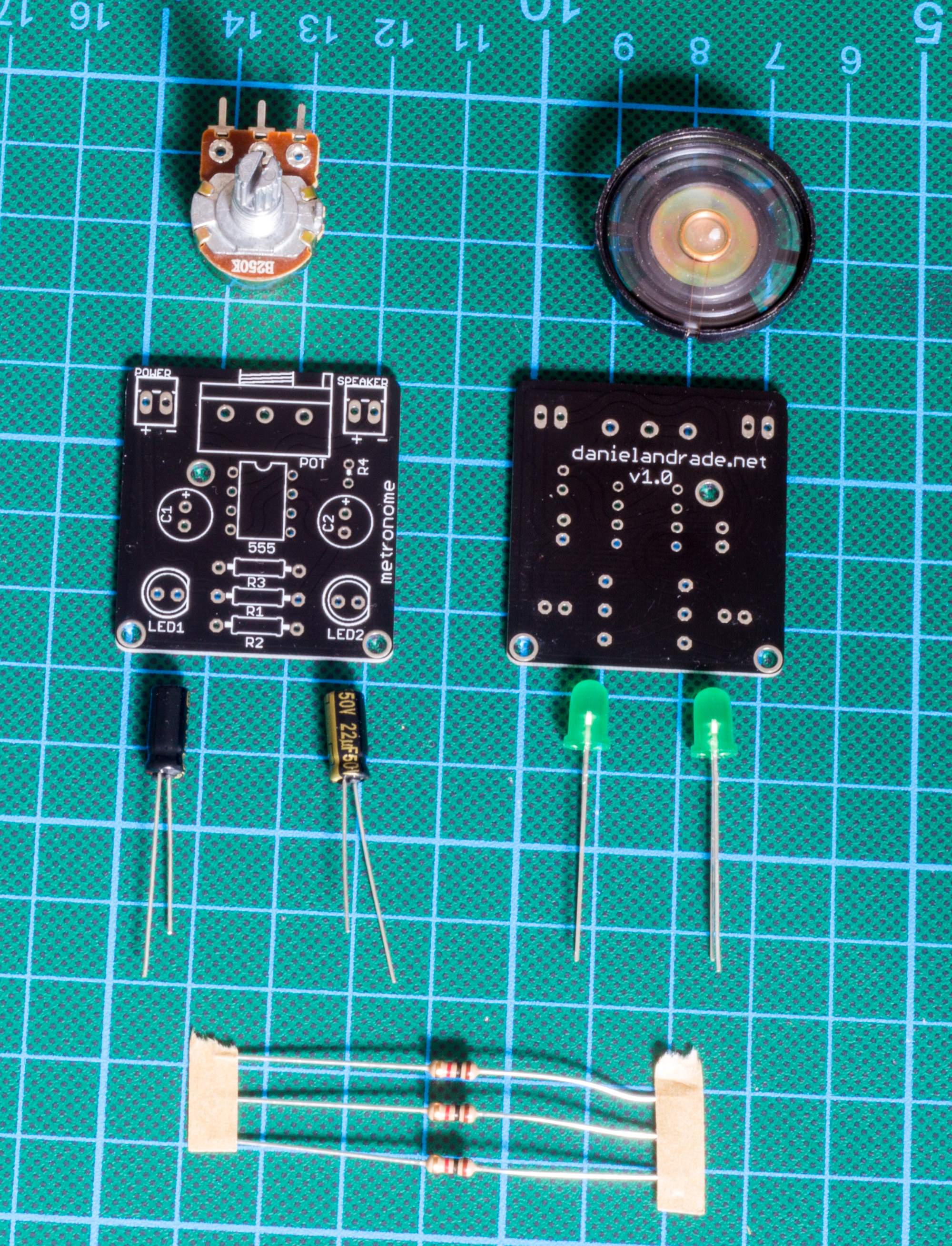
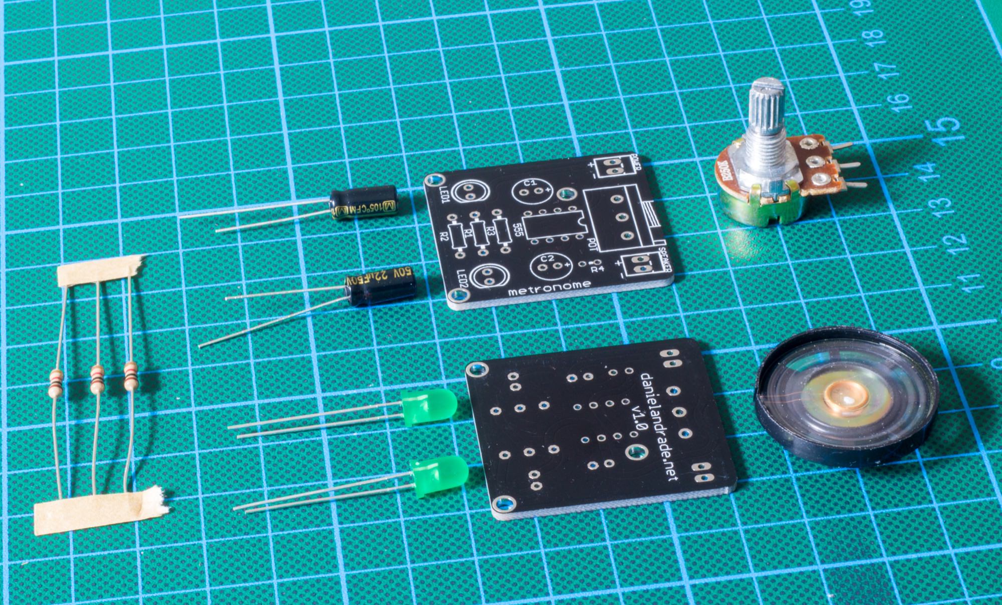
Component List #
- 1x 555 IC (with or without socket)
- 1x PCB
- 2x 22µF Capacitors
- 3x 1k Ohm Resistors
- 2x 5mm LED
- 1x 8 Ohm Speaker
- 1x 9v Battery or Power Supply
- 2x (Optional) Terminal Blocks for connecting the speakers and the battery
For the PCB, you can download the files for Eagle Cad on my Github repository. For this project, I chose to make the PCBs with PCBCart.com, they have really great quality and good prices!
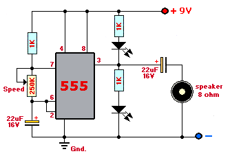
Schematics #
The schematics is the same one used back in 2007, the only difference is that I’ve added a jumper near the potentiometer, so that you can insert a fixed resistor in series with the pot to change the max/min resistance (and frequency).
PCB Design #
I wanted the board to be fun, so as you can see in the image below, all the traces are a bit round and crazy. Also, for the round edges, I used my technique explained in this video HERE.
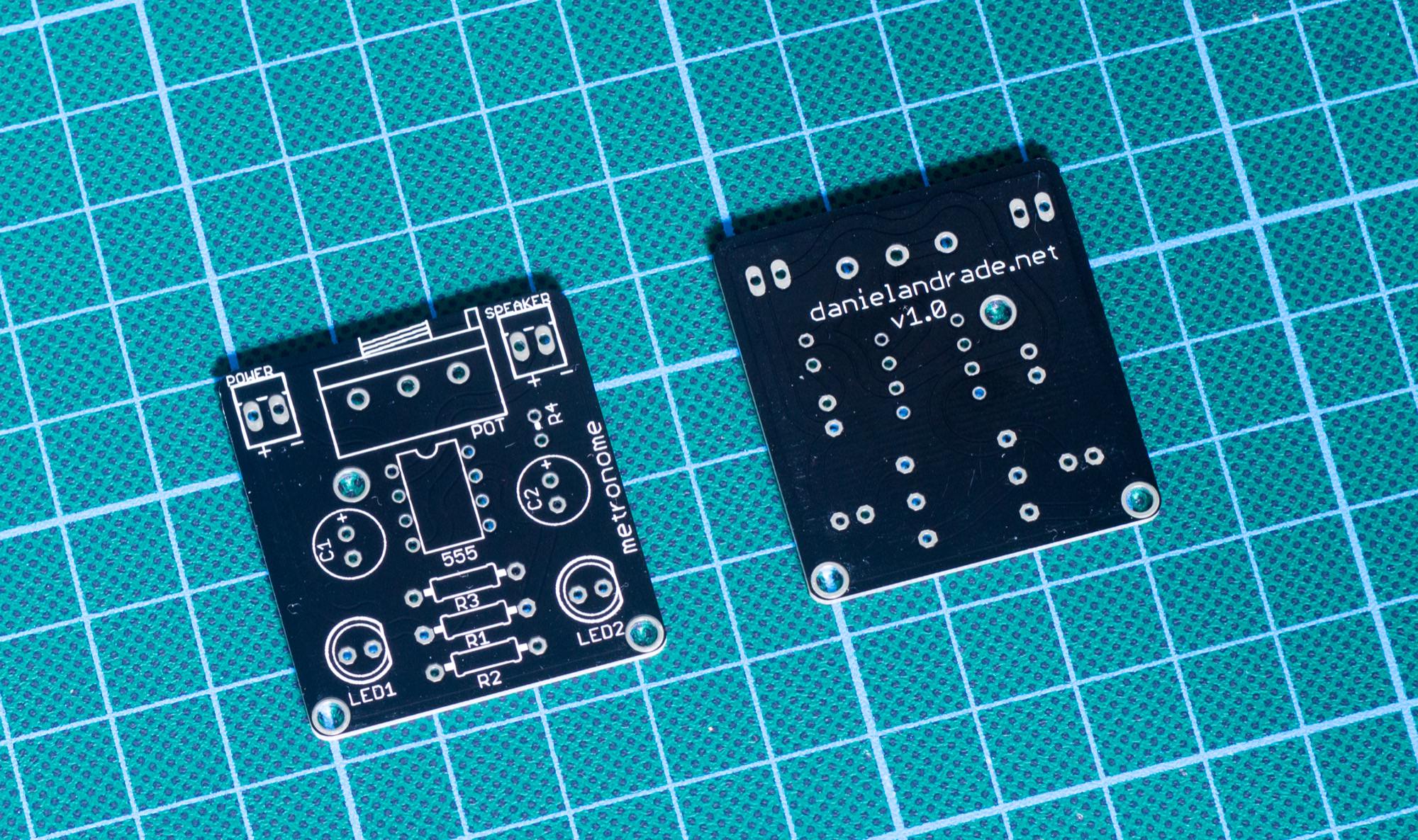
Note that in the picture above, the 555 IC is not present (more coming in the mail!).
In order to verify the polarity of components, you can check the PCB design out of EagleCad.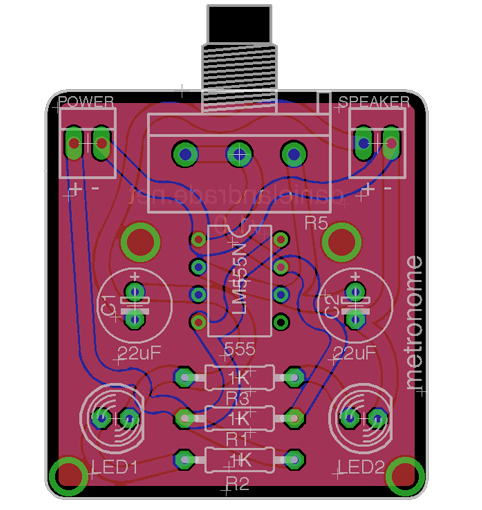
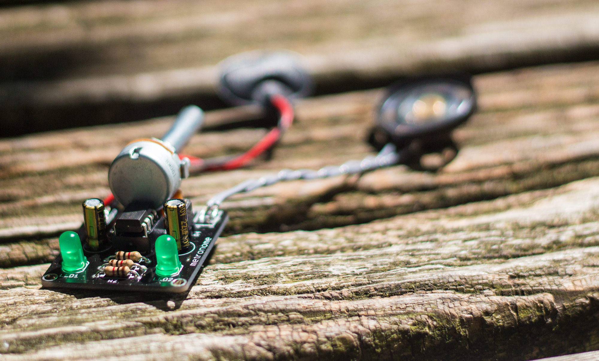
Video (because why not!)
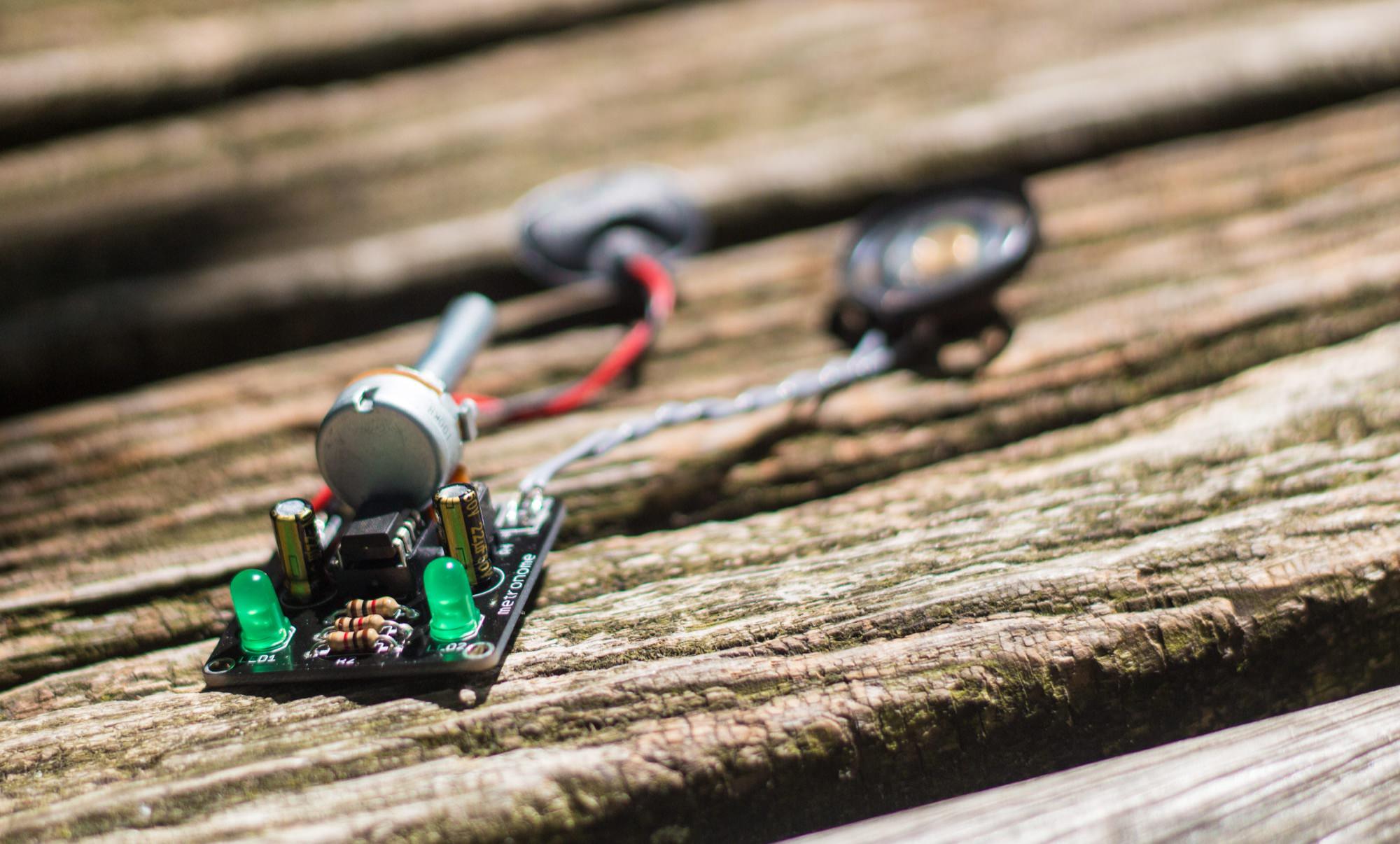
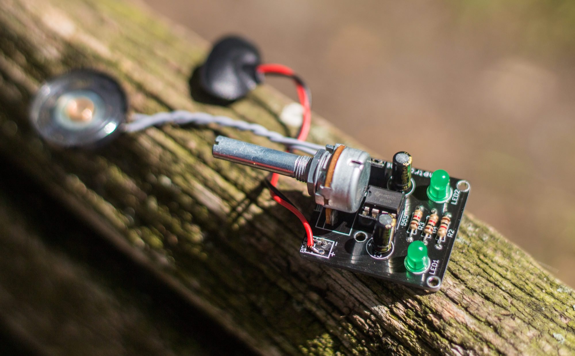
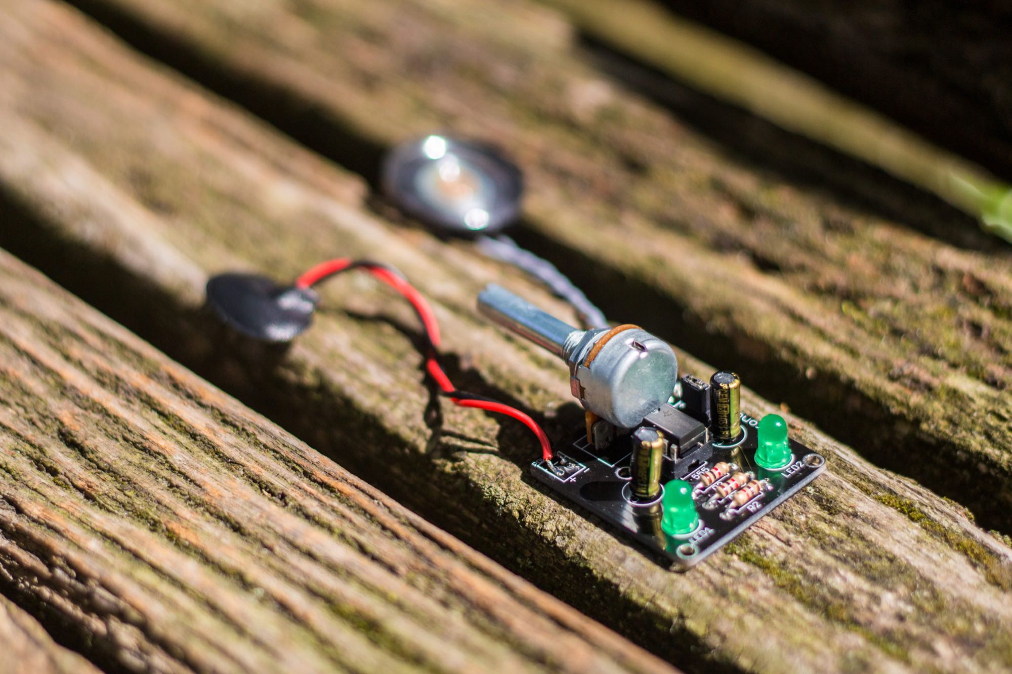
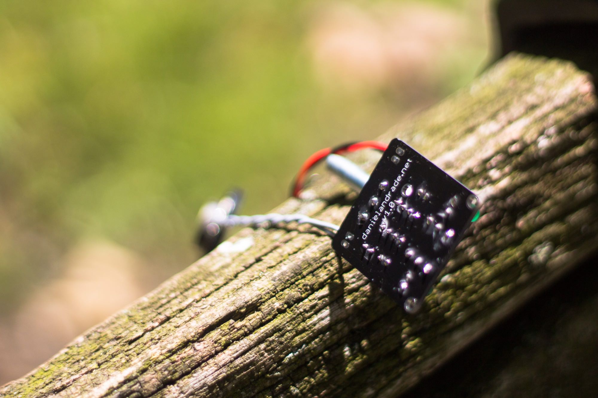
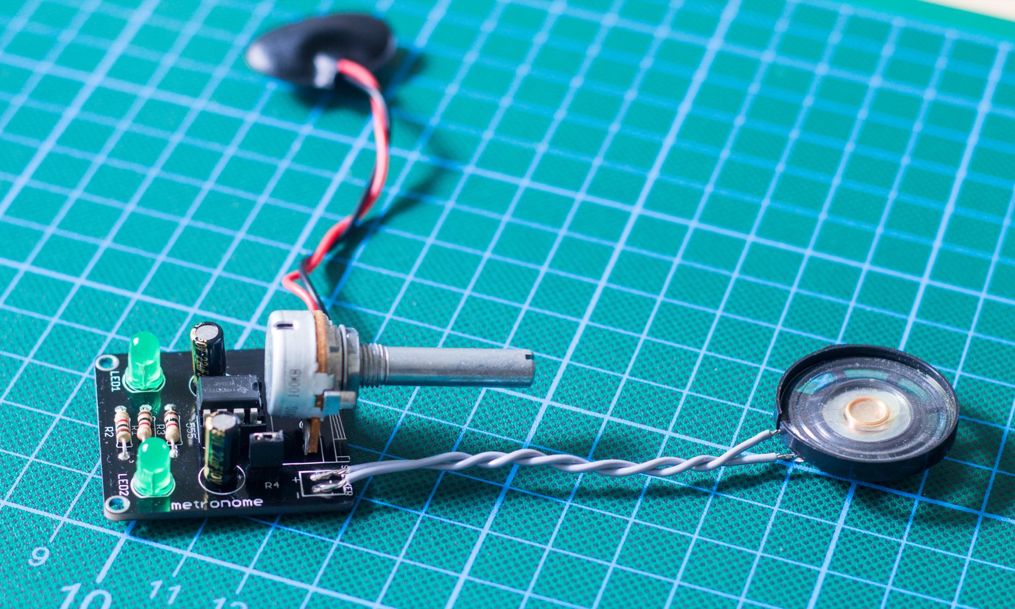
More pics #