HowTo: Blinking LEDs
Listening to music on my PC (proudly using WINAMP), I was wondering how it would be to have some LEDs blinking with the sound that came out from the P2 connector. So I decided to make a simple circuit to do that. It worked pretty well, so I decided to write a post with step-by-step instructions on how to do it. Hope you enjoy it!
Material and Equipment:
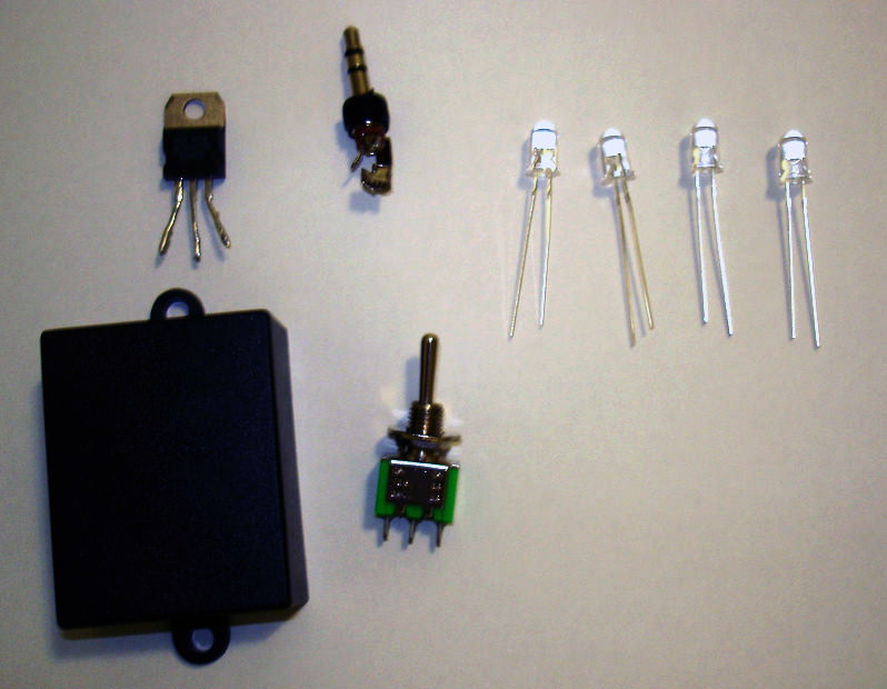
- 4 LEDs (any color)
- P2 plug
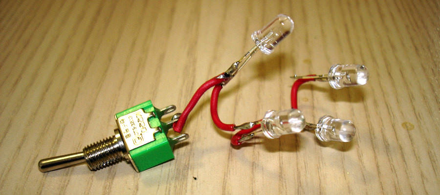
- 2 position switch
- TIP31 component
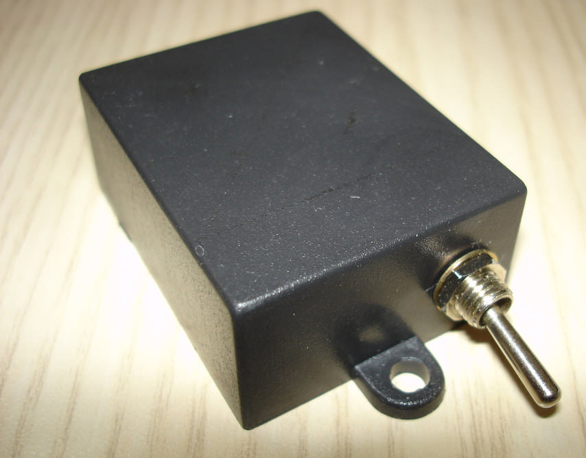
- Box to put all the stuff (if you want)
- Soldering iron and accessories
- Cable
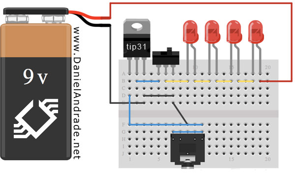
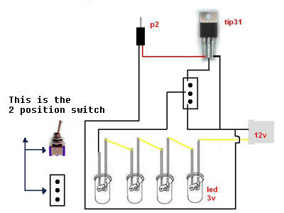
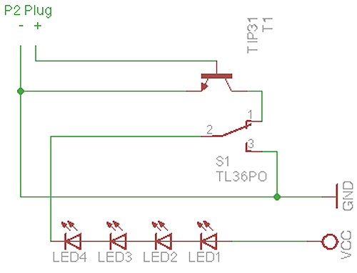
Here’s how this project works: You will connect 4 LEDs to the +12V power supply from your computer. These LEDs are soldered to a 2-position switch, which is then connected to a component called TIP31. The TIP31 component receives the audio signal intensity from the P2 connector and uses it to make the LEDs blink in sync with the music.
You can follow this schematic (there are 3 different ones to help you understand it).
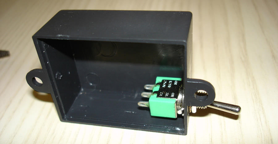
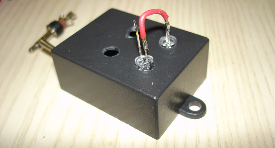
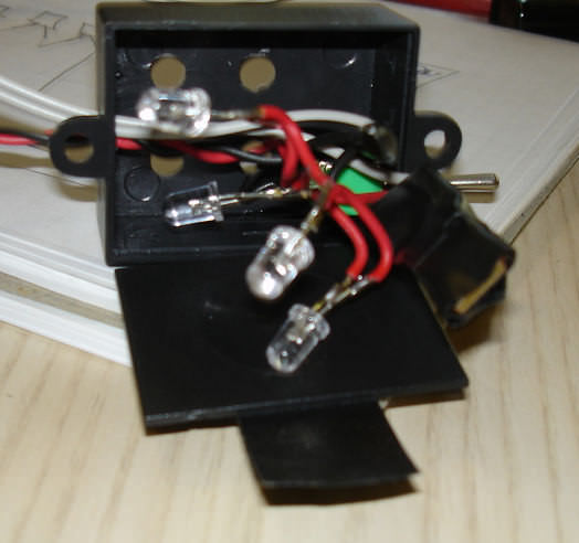
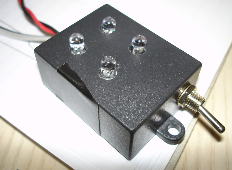
For this project, I decided to install everything inside a small black box I had here and made 6 holes in it. Four in the top for LEDs and one on each side for the switch and cables. You can follow the pictures:


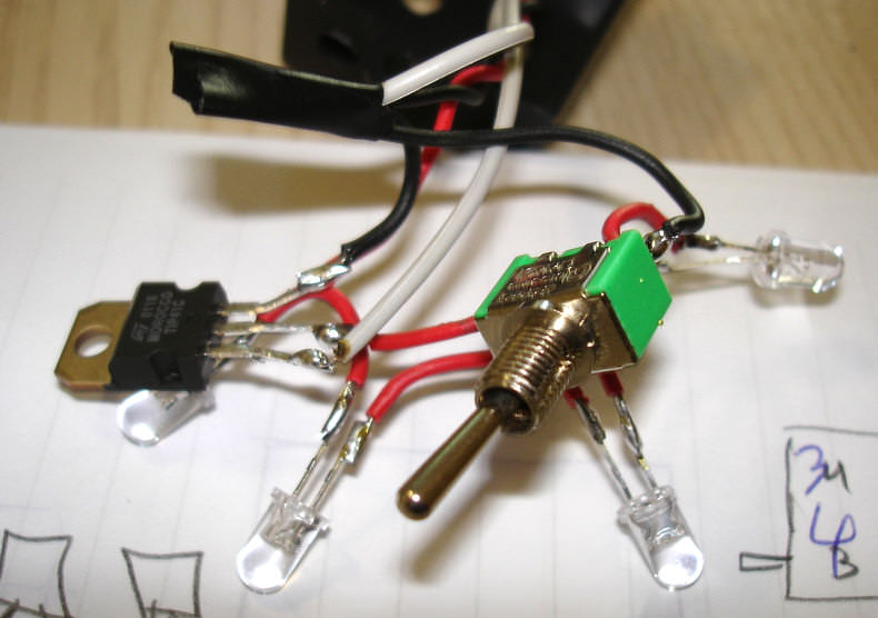
With the box ready, it’s time to connect everything. I started with the LEDs, soldering one small cable connecting each one, so it would be easier to arrange them inside the box after.
After connecting all of the LEDs, you must connect the cable coming from the LEDs to the center pin of the switch. One side of the switch goes to the middle pin of the TIP31 component, and the other one goes to the ground cable.
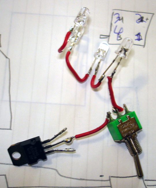
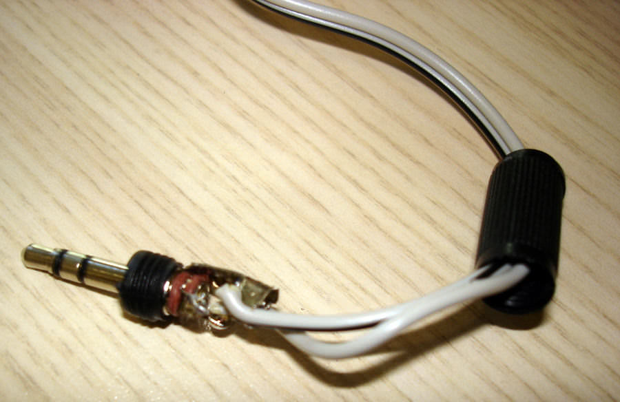
Now it’s time to make the P2 connector. You can see that the P2 connector has 3 pins, they are, left channel, right channel and ground. So you have to decide if you want the left or right channel and then connect it with the left pin from the TIP31. Remember that if you connect the P2 using the left channel, only the right is enabled on the computer and this circuit won’t work. Usually the ground pin is the bigger one, and the others are small and similar. You have to connect the ground from P2 connector to the right pin of the TIP31 (right pin from TIP31 is ground)
On the other pin from the switch, you must connect it to the ground from TIP31. If the switch is closing the circuit with the TIP31, the LEDs will only blink if there is a signal coming from the P2 connector, and if it’s in the other direction, the LEDs will always be ON.
Now it’s time to put everything together in the box. As you can see in this picture, it’s not very organized, but after closing the box, it’ll look much better.
Job is done!!

Obs: In this video, I made it with just one LED to see if it would really work.
Here is the video of the finished project:
I hope this guide was helpful in walking you through the process of building LED music visualizers! While I’ve tried to be thorough, there may be areas that could use more clarification.
If you build this project yourself, I’d love to hear how it went. Please feel free to share your experience, suggestions for improvements, or any questions in the comments below.
Thanks for reading and happy building!